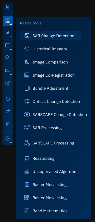
Vector Tools
The Vector Tools consists of tools that enable you to do a number of differents tasks namely:
- Layers Intersection
- Union Layers
- Layers Difference
Layers Intersection
The Vector Layer Intersection tool is used to extract spatial features that are common to two vector layers. It performs a geometric overlay operation to identify areas or features that exist in both layers, and outputs a new vector layer containing only those intersecting parts.
This operation is applicable to vector data types such as points, lines, and polygons, and is widely used in spatial analysis workflows to detect overlaps, shared boundaries, or jointly occupied spaces.
Prerequisites
Before using the Vector Layer Intersection tool, ensure the following:
- Both input layers must be vector layers (point, line, or polygon).
- The input layers are available in the Layers panel.
- The geometry types of the input layers are compatible for intersection.
- Both layers must be correctly georeferenced and aligned spatially.
Use Cases
| Use Case | Description |
|---|---|
| Overlap analysis | Identify areas where two zones or jurisdictions share common ground. |
| Shared infrastructure | Find where road networks intersect with pipelines, or where habitats overlap with utility lines. |
| Land use constraints | Determine where proposed development areas intersect with protected zones or hazard zones. |
| Spatial querying | Generate a new dataset containing only features that are spatially common to both input layers. |
Using Vector Layer Intersection Tool
In this section, you will learn how to use the Vector Layer Intersection tool.
To use the Vector Layer Intersection tool, do the following:
-
Go to the Analyst Tools panel, click the Vector Layer Intersection tool.
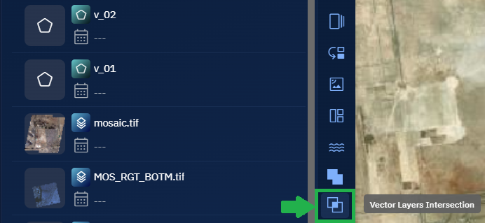
The Vector Layer Intersection dialog box is displayed.
-
On the Vector Layer Intersection dialog box:
- Select the First Vector Layer (v_01).
- Select the Second Vector Layer (v_02) to intersect with the first layer.
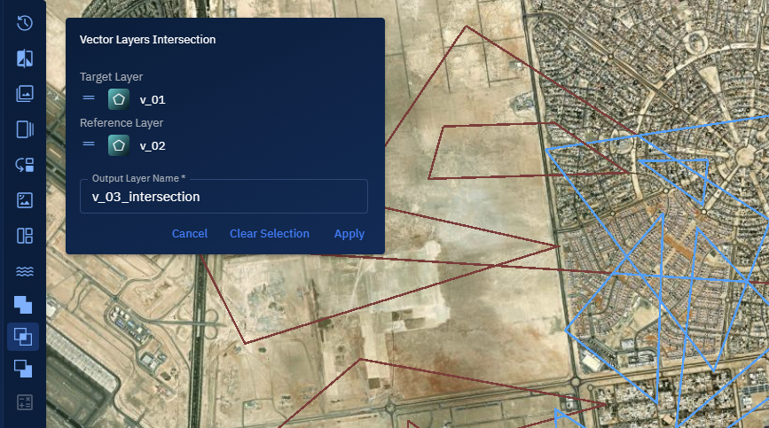
-
Click the Apply button to generate a new layer containing only features that exist in both input layers.
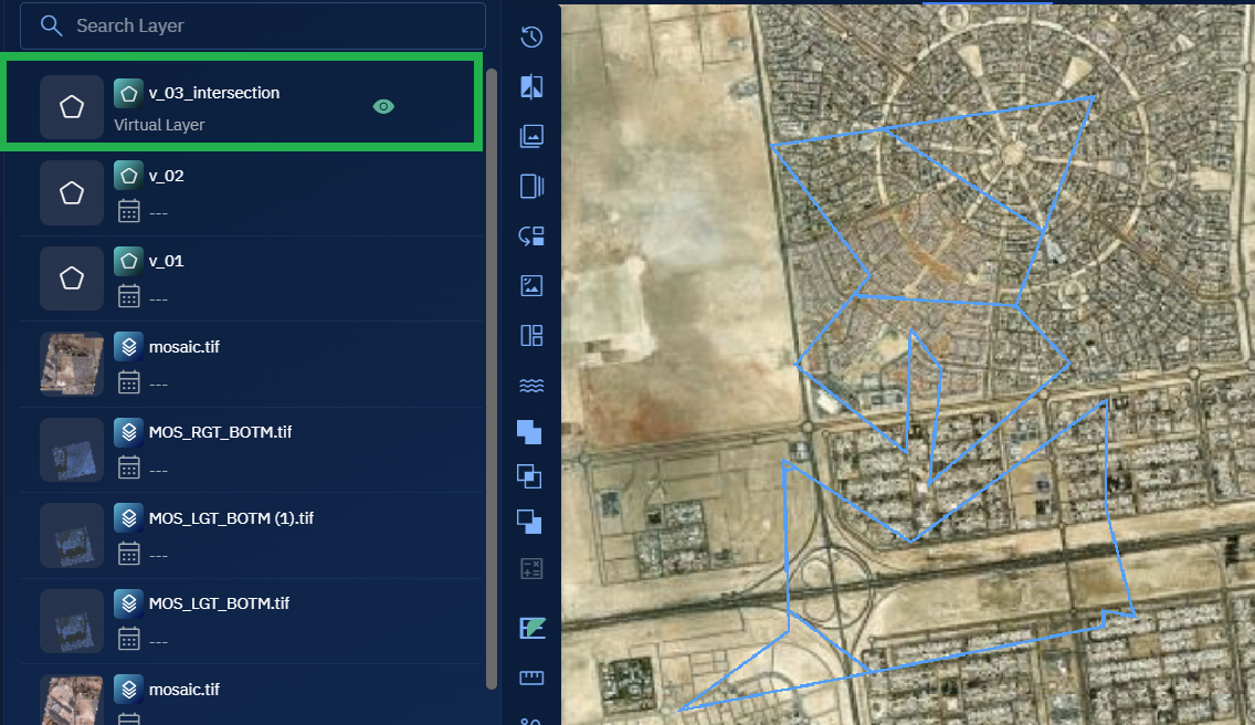
The resulting output layer is automatically added to the Layers panel. This layer contains only those spatial features where the two selected layers overlap.
-
Select the output layer, click the vertical three-dots menu, and then click the Zoom into Layer option. Proceed to view the features.
Union Layers
With the Union layers tool, you can combine vector features from two separate files into a single, unified output layer. You can merge overlapping features into one, while preserving non-overlapping features as individual entries in the same file.
This helps you build a complete dataset that represents both shared and unique geometries across sources—whether you're working with points, lines, or polygons.
Prerequisites
Before using the Vector Layer Union tool, ensure the following:
- Two input layers must be available in the Layers panel.
Use Cases
| Use Case | Description |
|---|---|
| Unified spatial data | Combine multiple vector layers into one consolidated layer for visualization or analysis. |
| Feature merging | Merge overlapping geometries into single features to eliminate redundancy. |
| Spatial completeness | Ensure no spatial data is excluded, even when input features don’t intersect. |
| Layer consolidation | Reduce multiple sources into one vector file for easier management and analysis. |
Using Union Layers
In this section, you will get to know how to use the Vector Layer Union tool.
To use the Union Layers tool, do the following:
-
Go to the Analyst Tools panel, click the Vector Layer Union tool.
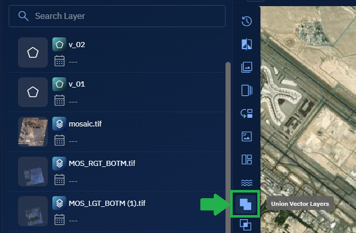
The Vector Layer Union dialog box is displayed.
-
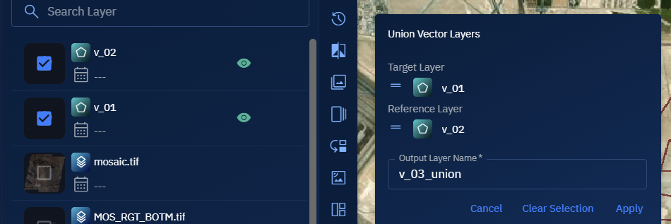
On the Vector Layer Union dialog box:
- Select the First Layer.
- Select the Second Layer to union with the first.
-
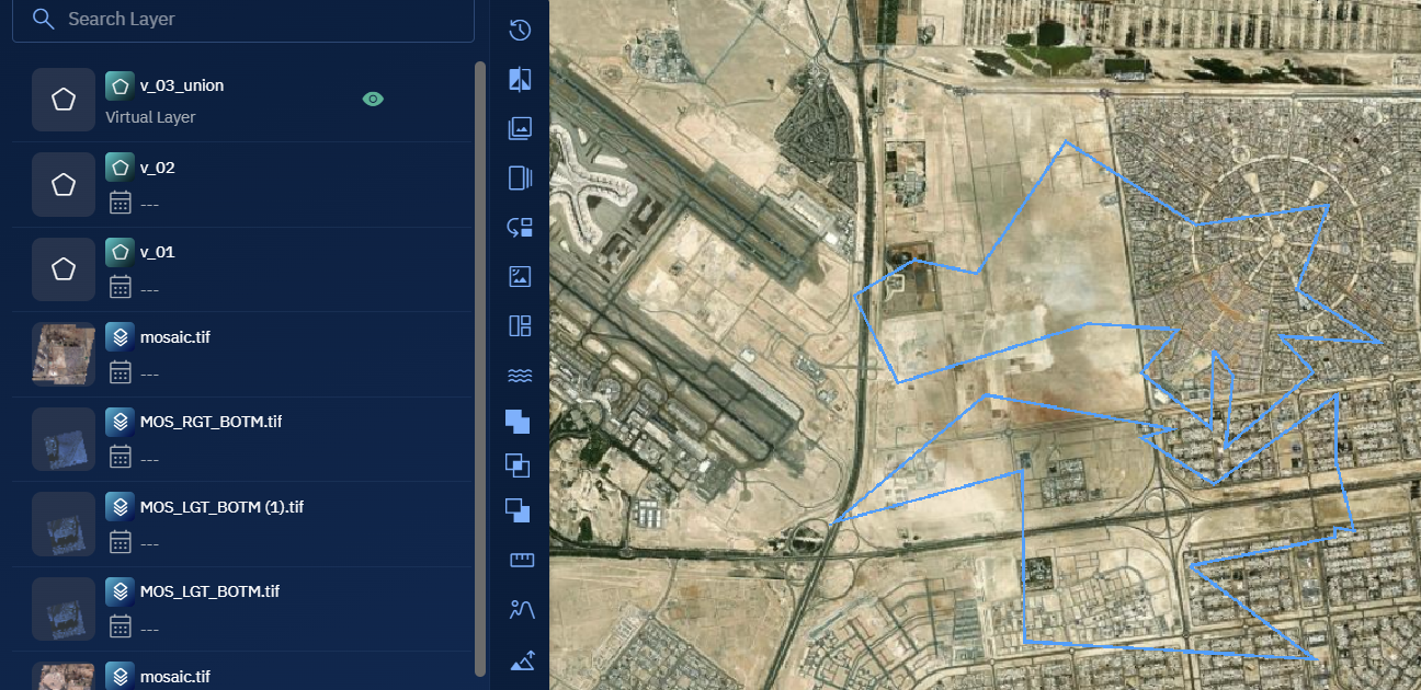
Click the Apply button to create a single output layer that merges overlapping features into one and retains non-overlapping features as separate entries.
-
Select the output layer, click the vertical three-dots menu, and then click the Zoom into Layer option. Proceed to review all the combined features on the map.
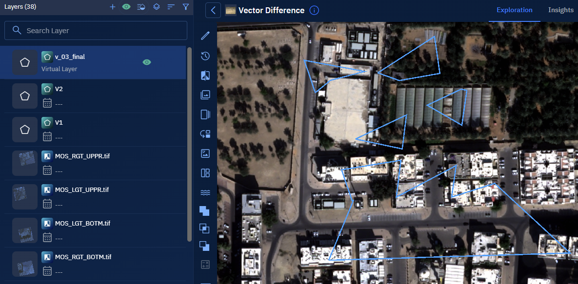
Layers Difference
The Layers Difference is used to identify unique features in the target vector layer that do not exist in the reference vector layer.
You can use this tool to perform a geometric subtraction operation, resulting in a new layer that contains only the features unique to the target.
This tool supports vector data types such as points, lines, and polygons, and is commonly used in spatial analysis to highlight areas of change, exclusion, or discrepancy between datasets.
Prerequisites
Before using the Layers Difference tool, ensure the following:
- Input layers are of the same geometry type (for example, both layers must contain polygons, lines, or points).
Use Cases
| Use Case | Description |
|---|---|
| Change detection | Identify new constructions, expansions, or land use changes by comparing updated survey data with baseline layers. |
| Data validation | Highlight discrepancies between a planned dataset and what actually exists on the ground. |
| Spatial cleanup | Remove overlapping or duplicate geometries from the target dataset based on reference standards. |
| Regulatory compliance | Ensure a proposed boundary or plan does not intrude into restricted zones defined in the reference layer. |
Using Layers Difference Tool
In this section, you will learn how to use the Layers Difference tool.
Configuring Parameters and Execute Job
To use the Layers Difference tool, do the following:
-
Go to the Analyst Tools panel, click the Vector Layers Difference tool.
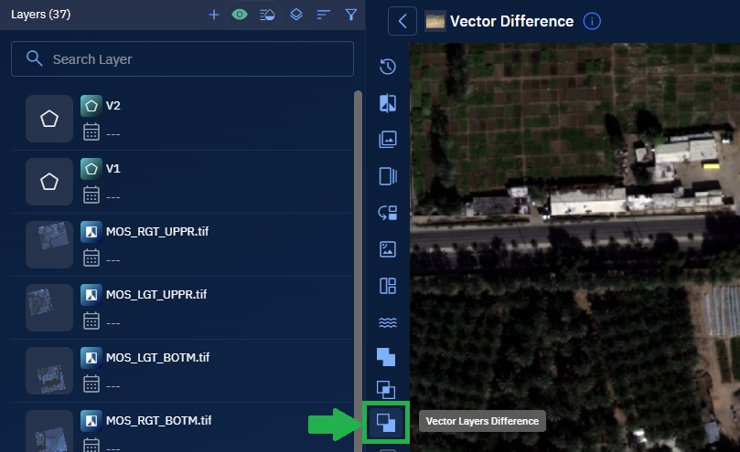
The Vector Layers Difference dialog box is displayed.
-
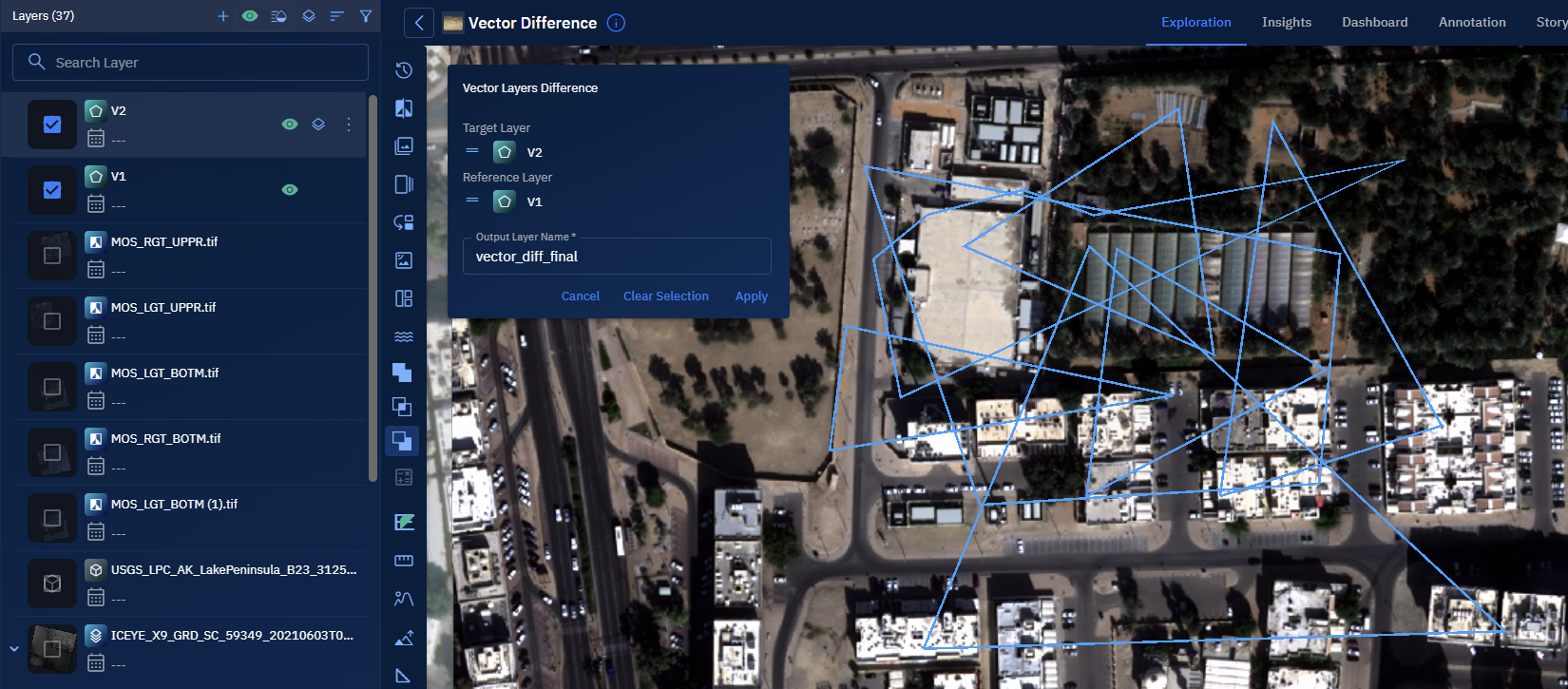
On the Vector Layers Difference dialog box:
- Select the Target Layer (the layer from which features will be subtracted).
- Select the Reference Layer (the layer whose features will be used to perform the subtraction).
-
Click the Apply button to run the difference operation.
A new output layer is generated containing features that exist in the target layer but not in the reference layer. This output is automatically added to the Layers panel for visualization and further analysis.
Monitoring Processing Pipeline
-
Click the Data module, select the Analytics sub-module, and then view the job progress in the In-Progress/Completed tab.

Once the job is successfully processed, it will be displayed in the Workspace.
Click the Eye icon to view details of the job.
Viewing and Validate the Results
-
Select the virtual output layer, click the vertical three-dots menu, and then click the Zoom into Layer option. Proceed to view the features.